Reference Manual
Chapter 6: Electrical/Interior: Rallye Pac Conversion
The standard Oldsmobile Cutlass instrument panel, with little
more than a speedometer, fuel gauge and a collection of "idiot" lights
leaves much to be desired for anyone with the least bit of interest in what is
happening under the hood. Fortunately, Oldsmobile offered, as an option, an
instrument panel that included a basic set of gauges and this instrument panel can
be swapped into a G-body that was originally equipped with the standard instrument
panel with some minor rework of the original wiring.
Parts required:
- "Rallye Pac" Gauge Cluster Assembly
- Water temp sender (single terminal)
- GP Sorenson p/n tsu64
- or
- the equivalent
- Oil sending unit for cluster with gauges
- GM p/n 14036243
- or
- GP Sorenson p/n ops88
- or
- the equivalent
- Brass extension for oil sender to clear the intake
manifold and cruise control bracket.
- GM p/n 401559
- or
- 1/8" NPT brass 45° elbow and a 2" long
1/8" NPT brass nipple
- or
- the equivalent
- 18awg wire
Tools required:
- 5.5mm socket
- 7mm socket
- 1/4" socket
Time required:
While not difficult, a few things related to this swap may take
some time to work out. Although it may take less time, plan on an afternoon to
complete this conversion.
Overview:
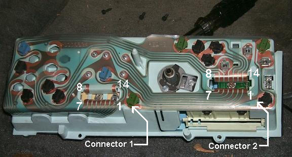
The standard Oldsmobile Cutlass instrument panel is wired
differently than the cluster with gauges. For this reason a swap from the standard
cluster to a Rallye Pac cluster will require the rearrangment of the terminals in
one of the cluster connectors.
| Standard Cluster |
|
|
Connector 1: |
Connector 2: |
|
| 1. |
Service Engine Soon Ind. |
Yel |
1. |
LH Turn Indicator |
Lt. Blu |
| 2. |
(Blank Indicator) |
|
2. |
Ground |
Blk |
| 3. |
(Blank Indicator) |
|
3. |
Illumination |
Gry |
| 4. |
(2nd Coolant Temp Ind.) |
|
4. |
Charge Indicator |
Brn |
| 5. |
(2nd Coolant Temp Ind.) |
|
5. |
Illumination |
Gry |
| 6. |
(Wait Indicator) |
|
6. |
Ground |
Blk |
| 7. |
(2nd Fasten Belts Ind.) |
|
7. |
Fuel Gauge |
Pnk |
| 8. |
(Water in Fuel Ind.) |
|
8. |
RH Turn Indicator |
Dk. Blu |
| 9. |
Not Used |
|
9. |
Fasten Belts Indicator |
Yel |
| 10. |
Not Used |
|
10. |
Brake Indicator |
Tan/Wht |
| 11. |
Not Used |
|
11. |
Coolant Temp Indicator |
Dk. Grn |
| 12. |
Not Used |
|
12. |
Ignition Input |
Pnk/Blk |
| 13. |
Not Used |
|
13. |
Oil/Choke Indicator |
Tan |
| 14. |
(Low Fuel Indicator) |
|
14. |
Hi Beam Indicator |
Lt Grn |
| Gauges Cluster |
|
|
Connector 1: |
Connector 2: |
|
| 1. |
Service Engine Soon Ind. |
Yel |
1. |
Illumination |
Gry |
| 2. |
(Blank Indicator) |
|
2. |
Ground |
Black |
| 3. |
(Blank Indicator) |
|
3. |
Fuel Gauge |
Pnk |
| 4. |
Coolant Temp Indicator |
Dk Grn/Yel |
4. |
Oil Pressure Gauge |
Tan |
| 5. |
Ignition Input |
Pnk/Blk |
5. |
Fasten Belts Indicator |
Yel |
| 6. |
(Wait Indicator) |
|
6. |
Brake Indicator |
Tan/Wht |
| 7. |
(2nd Fasten Belts Ind) |
|
7. |
Coolant Temp Gauge Input |
Dk Grn/Wht |
| 8. |
(Water in Fuel Ind.) |
|
8. |
(Oil/Choke Indicator) |
|
| 9. |
Not Used |
|
9. |
Charge Indicator |
Brn |
| 10. |
Not Used |
|
10. |
Ignition Input |
Pnk/Blk |
| 11. |
Not Used |
|
11. |
Hi Beam Indicator |
Lt Grn |
| 12. |
Not Used |
|
12. |
LH Turn Indicator |
Lt Blu |
| 13. |
Not Used |
|
13. |
RH Turn Indicator |
Dk Blu |
| 14. |
(Low Fuel Indicator) |
|
14. |
Tachometer Input |
Wht |
From the above charts, the first thing you might notice is that
all functions use the same color code for each function wire, for both clusters.
Not quite so obvious at first glance, the standard cluster uses 2 each of the
illumination and ground leads, whereas the gauges cluster uses only one of each.
This means that when doing this swap you'll have an extra
ground and an extra illumination wire. Because for both clusters each connects to
the same location in the wiring harness and all are of the same gauge, which of
each you use for the swap is irrelevant and the extra of each wire will need to
protected from shorting out and stuffed away behind the dash.
The Procedure:
- The first step is to remove
the original cluster.
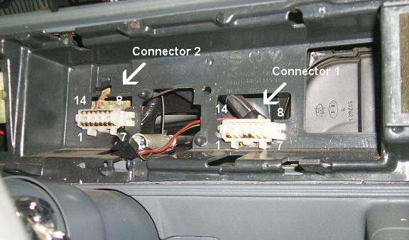
- With the original cluster removed, push the locking tabs on
either side of connector 2 toward the center of the connector and push the
connector in so that it passes through the instrument panel adaptor.
- Connector 2 can then be passed through the larger opening
above it's installed location and pulled away from the i.p. adaptor so that you
can gain access to the terminals.
- Each terminal is secured in the connector shell by a locking
tang. To remove a terminal you must insert a small pick, awl, jewelers
screwdriver or similar tool between the terminal and the connector shell to
depress the tang, releasing the terminal. With the tang depressed, the terminal
will pass through the shell by pulling on the wire. Do not use force!
When the tang has been sufficiently depressed the terminal will pull
out easily with little to no effort.

- While the terminals are removed, inspect each terminal
closely for any corrosion or tarnish. If any corrosion or tarnishing is present,
remove it using an eraser or a cloth soaked in rubbing alcohol. Do not use an
abrasive, each terminal is steel with a thin copper coating, the use of an
abrasive will degrade the copper coating allowing the steel terminal to corrode.
- Rearrange the terminals in Connector 2 by color code using
the chart below:
| Connector 2 |
|
|
Standard Cluster: |
Gauges Cluster: |
|
| 1. |
LH Turn Indicator |
Lt Blue |
1. |
Illumination |
Gray |
| 2. |
Ground |
Black |
2. |
Ground |
Black |
| 3. |
Illumination |
Gray |
3. |
Fuel Gauge |
Pink |
| 4. |
Charge Indicator |
Brown |
4. |
Oil Pressure Gauge |
Tan |
| 5. |
Illumination |
Gray |
5. |
Fasten Belts Indicator |
Yel |
| 6. |
Ground |
Black |
6. |
Brake Indicator |
Tan/Wht |
| 7. |
Fuel Gauge |
Pink |
7. |
Coolant Temp Gauge Input |
Dk Grn/Wht |
| 8. |
RH Turn Indicator |
Dk Blue |
8. |
(Oil/Choke Indicator) |
|
| 9. |
Fasten Belts Ind. |
Yellow |
9. |
Charge Indicator |
Brown |
| 10. |
Brake Indicator |
Tan/Wht |
10. |
Ignition Input |
Pnk/Blk |
| 11. |
Coolant Temp Indicator |
Dk Grn |
11. |
Hi Beam Indicator |
Lt Grn |
| 12. |
Ignition Input |
Pnk/Blk |
12. |
LH Turn Indicator |
Lt Blu |
| 13. |
Oil/Choke Indicator |
Tan |
13. |
RH Turn Indicator |
Dk Blu |
| 14. |
Hi Beam Indicator |
Lt Grn |
14. |
Tachometer Input |
Wht |
- When reinserting the terminals into the connector shell, it
is very important that the tang be bent away from the terminal so that it will
be able to properly secure the terminal in the shell. If this is not done, or
done improperly, it's likely that the terminal will slip out of position in the
connector shell and make poor, or no, contact with the cluster. Resulting in
inaccurate, or non-functional gauges or functions. An easy way to check each
terminal is to push on them as if removing them from the housing, if the tang is
holding the terminal in the housing, the terminal will only move a short
distance in the connector housing.
- Looking at the chart above, you'll notice that the Standard
Cluster uses 2 each of the Illumination and Ground wires, while a Gauges Cluster
uses only one of each. The spare of each of these lead wires should be protected
from shorts (such as with electrical tape) and securely fastened to the wiring
harness behind the cluster to prevent future problems.
- This will leave 2 circuits that will require special
attention:
- The Tachometer
- Method 1 (Recommended)
- Install a wire, with terminal, in Connector 2,
position 14 (White to match factory color, ideally)
- Route this wire through the firewall to the
distributer
- Attach a 1/4" Quick Disconnect terminal to
the wire and plug this QD terminal into the Distributer TACH
terminal
- Method 2 (The cleanest)
Check
your distributer, if there is already a white wire connected to the
TACH terminal, you could use this method.
- Install a wire, with terminal, in Connector 2,
position 14 (White to match the factory color, ideally)
- Remove the two screws from the opposite corners
of the fuse block
- Pry out the tabs at each corner to seperate the
fuse block from the bulkhead connector.
- From under the hood, loosen the 1/4"
captive screw in the center of the bulkhead connector holding the
two halves of the buckhead connector together.
- Pull the bulkhead connector apart
- Obtain a proper terminal for the bulkhead
connector and attach it to the end of this wire
- Insert the terminal into the bulkhead connector
at position A7
- Reassemble the bulkhead connector and the fuse
block
- The Coolant Temperature Sensor
- Method 1 (Recommended)
- Insert the existing Dk Green wire into Connector
2, position 7
- Remove the original Coolant Temperature Sensor
- Install the Sensor listed in the Parts list or
it's equivalent
- Method 2 (Harder)
This method will alleviate the need to change the Coolant Sensor if your
engine has a two terminal Coolant Sensor.
- Remove the two screws from the opposite corners
of the fuse block
- Pry out the tabs at each corner to seperate the
fuse block from the bulkhead connector.
- From under the hood, loosen the 1/4"
captive screw in the center of the bulkhead connector holding the
two halves of the buckhead connector together.
- Pull the bulkhead connector apart
- Remove the terminal at D5 (Dk Green or Dk
Green/Yellow)
- Reinstall this terminal at location C6
- Reassemble the bulkhead connector and the fuse
block
- Method 3 (The most difficult)
Warning: This method will irrevocably alter your wiring harness.
Because the wiring harness is no longer available new from GM, this
method should only be used after very careful consideration, and is not
recommended.
This method will give you a functional coolant temp gauge and a
functional coolant temperature indicator.
- Extend the Dk Green wire at the Cluster
Connector 2, position 11 of the standard cluster to reach Connector
1 and install in position 4 (this maintains the bulb test function
of the coolant temp indicator).
- Modify the Ignition input lead, Pink/Black, to
also connect to Connector 1, position 5, and install.
- Insert a new wire lead, with terminal, into
Connector 2, position 7 (Dk Green/White to match the factory color,
ideally).
- Remove the two screws from the opposite corners
of the fuse block
- Pry out the tabs at each corner to seperate the
fuse block from the bulkhead connector.
- From under the hood, loosen the 1/4"
captive screw in the center of the bulkhead connector holding the
two halves of the buckhead connector together.
- Pull the bulkhead connector apart
- Obtain a proper terminal for the bulkhead
connector and attach it to the end of this wire lead.
- Insert this wire terminal into the bulkhead
connector at position C6
- Reassemble the bulkhead connector and the fuse
block
Installing the Oil Pressure Sender
- Disconnect the lead wire from the Oil Pressure Switch.
- Remove the original Oil Pressure Switch.
- Install the brass extension.
- Install the Oil Pressure Sender.
- Connect the original lead wire to the Oil Pressure Sender.
Optional method to keep the Oil Pressure Switch and
indicator functional:
- Disconnect the lead wire from the Oil Pressure Switch.
- Remove the original Oil Pressure Switch.
- Install a 1/8" brass hex nipple in the block.
- Attach a brass 45° elbow to the nipple.
- Attach a brass Tee to the elbow.
- Install the Oil Pressure Switch in the upper port of the
Tee.
- Install the Oil Pressure Sender in the remaining port of the
Tee.
- Connect the original lead wire to the Oil Pressure Sender.
- Connect a new lead wire to the Oil Pressure Switch and route
the wire to cluster connecter 2 and install in position 8.
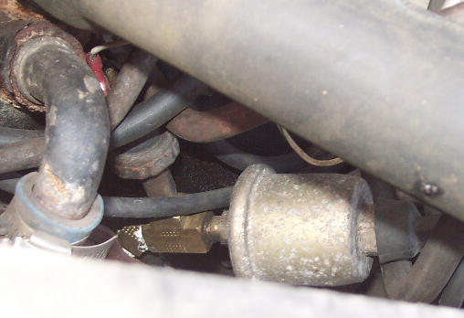
oil pressure sender and switch installed
Setting the Tachometer:
The tachometer can be set to indicate RPM for a 6 or 8 cylinder
engine by means of a jumper accessible from the rear of the gauge cluster housing.
- 1. Instrument Cluster Assembly
- 2. Shorting Adapter
-
- Calibrate the tachometer by installing the shorting
adaptor in the hole that matches the number of engine cylinders (6 or 8).
- or
- This would be a good time to consider replacing the jumper with a
soldered connection to eliminate possible
future problems.
Addressing the issue of the Odometer:
- The Legal Situation:
When replacing a speedometer assembly, the law requires the odometer reading of
the replacement unit to be set to register the same mileage as the prior
odometer. If the same mileage cannot be set, the law requires that the
replacement odometer be set to zero and a label be installed on the driver's
door frame to show the previous odometer reading and the date of replacement.
- Now the good news. The odometer assembly used in a standard
cluster is identical to that used in the gauges cluster.
Cleaning the gauge faces:
- Don't do it. The ink used to print the
gauge face is water based. A liquid based cleaning fluid, or even water, will
smear the printing or even completely remove the printing.
|
Table of Contents
|
|
Top of Chapter
|
|
|
Copyright © 1998-2024 by The Members of The Oldsmobile Mailing List. All
Rights Reserved. This web site is not affiliated with General Motors or
Oldsmobile. General Motors and Oldsmobile are trademarks of their respective
companies. The owners and members of this site are not responsible for errors
or inaccuracies.
|