Reference Manual
Chapter 6: Power Passenger Seat
Article by: Greg Smith
Reference Manual
Article by: Greg Smith
Since my wife approves of most of the expenditures on this car and since Olds was supposed to be the poor mans Caddy... I thought... I have a Power Seat on my side, my wife needs one too!
Power Passenger Seat! How hard could this be.... I just buy a track from a wrecker (there are LOTS out there) and I'll just wire her up...
Not so fast. Although I thought this wouldn't be a difficult task, you end up fabricating parts that don't really exist... And even though I have about 10 Hours into this project alone it is fairly cheap to do. Power racks (the rack and pinion part) are cheap and fairly rugged. Most yards will throw in the motor, wires and switch in for nothing, ask for a discount for "no returns". My rack, motor and harness cost $50CAN. I had to buy an extra switch for $20CAN from a different wrecker. The switches are rebuild-able so buy one that looks nice over a beat-up one that works. I'll post on a different page how to fix them... You will also need two 12V 30A SPDT relays and sockets. I paid $15CAN for these parts. Most electronic component stores have these. So for less than $100CAN I have power on the Passenger side too!....

First, here is a list of what tools you will need to complete this:
Build a power tool from the connector under the seat in the donor car

Bring a 12-14V cordless tool battery and use this to move the seat full up. This tests the motor and switch and moves the seat so you can access the bolts.
Remove the racks from the floor and then the seat from the racks.
Reshape Rack Flanges.

The reason you want 40/60 split seat and not bucket ones is that both sides of the 60/40 look like the end above
You need to cut and weld it so that it looks like:

See how the outboard flange is 1" narrower on the bucket seats.
Before you weld, DISASSEMBLE the racks, they have internal plastic bits that will not tolerate a lot of heat (welding)
Cut and weld the rear flange:


Cut and weld the front flange, you need to move the "big" hole inboard 1":
Or make this:

Look like this:


If you were unable to get a motor drive from a bucket seat... The "flex" drives will also be 1" too long. I managed to shorten them with my TIG welder on its lowest setting. The Flex cables can be disabled by tapping out the flex cable from the end with the WHITE PLASTIC RETAINER. Not the grey metal one... Sorry no pictures here.
You need to shorten the Aluminum Bracket that holds the motor by one inch. either cut out a one inch bit with your die grinder and TIG weld it or just drill a new hole and cut one inch off of the small end
Re-assemble the rack and attach it to the seat.
Wiring:
Wiring Harness and Relays
Of course the passenger side switch is an ultra rare thing, only coming on vista cruisers and not many of those... Long since discoed by GM. The Driver Side will work if you reverse the polarity on the motor and install it upside down...

Except....
Now everything works except that forward and back are backward
Relays to the rescue!
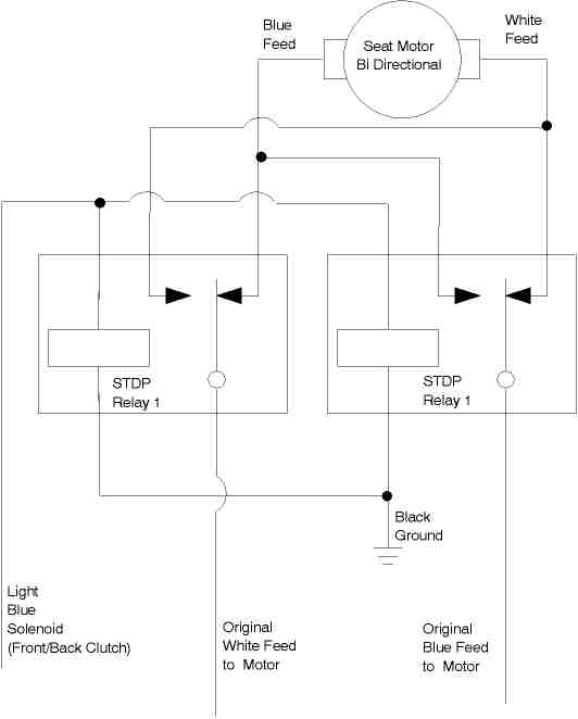
Install two SPDT relays (to fake a DPDT) That activate with the "forward and backward clutch" (light blue wire on my car)

Here is a better shot of the motor hook up. From the relays you have the stock white and blue (that are reversed) that do everything except forward and back. These directions are "driven" by the orange wires.

Cut hole for switch
Using the driver side hole, make a template for the hole that the switch needs
Flip it over, Mirror Image remember and use your die grinder to cut the hole in the passenger seat plastic
This is the only part that is not reversible. You have one shot to get this right.
Template:

Install Seat in the Car
Spice the power wire (Orange) and use your "connector tool" as the new connector for the passenger side
I grounded the passenger side similar to the Driver, on the cross car brace.
Wiring Diagram
| Table of Contents | Top of Chapter | |
|
|
||
| Copyright © 1998-2024 by The Members of The Oldsmobile Mailing List. All Rights Reserved. This web site is not affiliated with General Motors or Oldsmobile. General Motors and Oldsmobile are trademarks of their respective companies. The owners and members of this site are not responsible for errors or inaccuracies. | ||