Reference Manual
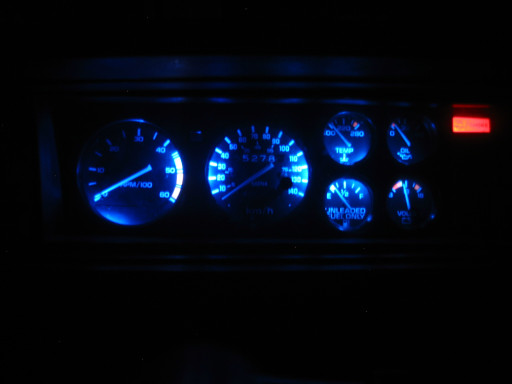
Chapter 6: LED Instrument Lighting
Article by: Sebastian Ducasse
Reference Manual
Article by: Sebastian Ducasse
The first thing to do is remove the cluster from the dash.
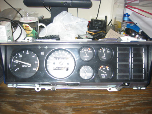
Once you have the cluster out you will need to remove the front plastic cover and the black metal one.
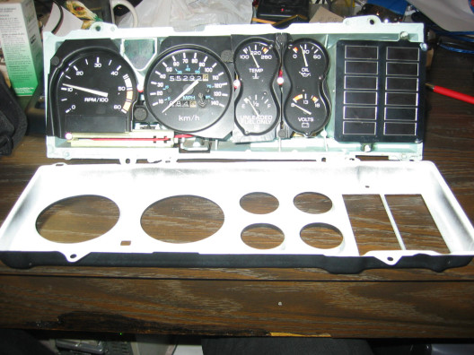
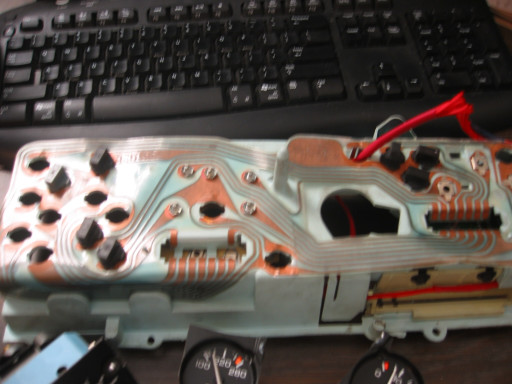
Then you need to carefully remove the gauges from the plastic case.
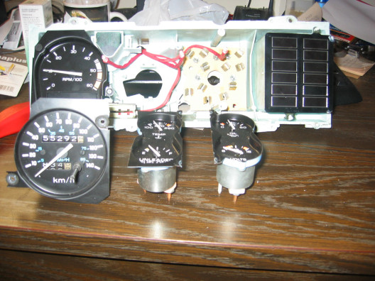
Remove all the bulbs you won't need anymore
Now you will need to assemble your LEDs. Take an LED and
figure out what side is positive and the other negative. The longest leg of an LED
is positive (anode; a), and the shortest leg is negative (cathode; k).
Another way of checking which side is positive or negative is by looking on the
side on the LED. The side that has a flat side on the bottom is the negative
side / leg.
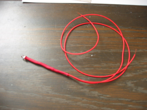
Now you need to solder the resistor to the anode leg ( very important that you use one resistor per led, the rating I gave is for only one led ).
Then run 2 lengths of wire from the ends, and use shrink tubing so as to not have any contact between each leg. What I did is run one tube around one leg then the next tube around both legs so I looks like this:
Now I would suggest you test you LEDs before you close everything up by using a 9 volt battery (only do this if you have the resistors on).
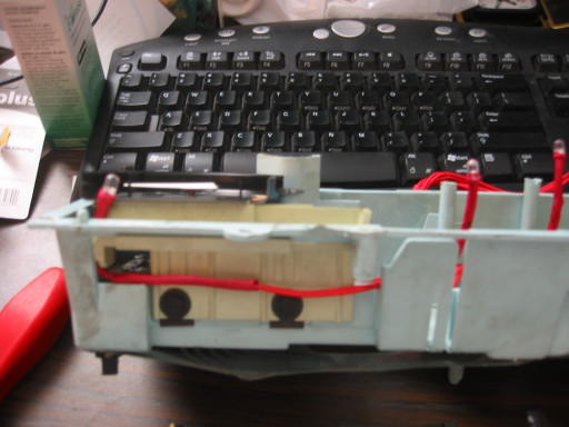
Now once you have made at least 4 of em you can run your LEDs
in the cluster case, you can put what ever way you want but I found this was the
best for me:
Now I would suggest you test your LEDs before you close everything up by using the 9 volt battery
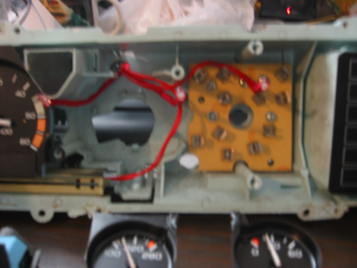
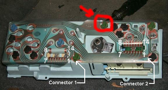
Once you have placed your leds all the wires should come out here:
I painted the inside of my metal cover black on one side and white on the inside to help reflect the light better:
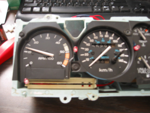
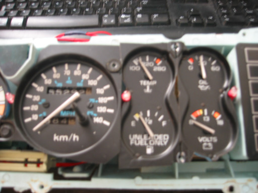
Now close it all back up, do one more light check with the 9 volt battery and then put back in the dash
And run them to your power source thru here:
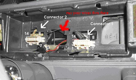
Run your power to any 12v source ( I used a block off my fuse box ) and a good ground as well
I put this together based on my own experience and in no way take resposibiliy for damages this may cause on your dash cluster if you are not in any way comfortable in doing this on your own ... i suggest you dont.
| Table of Contents | Top of Chapter | |
|
|
||
| Copyright © 1998-2025 by The Members of The Oldsmobile Mailing List. All Rights Reserved. This web site is not affiliated with General Motors or Oldsmobile. General Motors and Oldsmobile are trademarks of their respective companies. The owners and members of this site are not responsible for errors or inaccuracies. | ||